

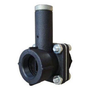
Limiting Orifice Valve Manual Gas Adjuster GAF
- Sizes: ½” to 4”
- Viton seal
- Max. pressure = 5 PSI
- Min. fluid temperature = -20°F
- Max. fluid temperature = 360°F
Learn More:
Description Documentation Ordering Information
Ordering Information
Ordering Information |
Alternate Product |
|||||||||
| Model | Price | Cart | Model | Lead Time | Order | |||||
| Model 4GAF4 Inlet: ½"; Outlet: ½"; Connection: NPT |
NV1.N | |||||||||
| Model 6GAF6 Inlet: ¾"; Outlet: ¾"; Connection: NPT |
NV2.N | |||||||||
| Model 8GAF8 Inlet: 1"; Outlet: 1"; Connection: NPT |
NV3.N | |||||||||
| Model 10GAF10 Inlet: 1¼"; Outlet: 1¼"; Connection: NPT |
NV35.N | |||||||||
| Model 12GAF12 Inlet: 1½"; Outlet: 1½"; Connection: NPT |
NV4.N | |||||||||
| Model 16GAF16 Inlet: 2"; Outlet: 2"; Connection: NPT |
NV6.N | |||||||||
| Model 20GAF20 Inlet: 2½"; Outlet: 2½"; Connection: ANSI (Weld) |
||||||||||
| Model 24GAF24 Inlet: 3"; Outlet: 3"; Connection: ANSI (Weld) |
||||||||||
| Model 32GAF32 Inlet: 4"; Outlet: 4"; Connection: ANSI (Weld) |
||||||||||
Description
GAF gas adjusters are designed to provide accurate flow control. The conical needle or cylindrical plug valve has a micrometric adjusting stem, allowing excellent regulation capabilities even at reduced flows. A common screwdriver is used to perform adjustments with the GAF; no special tools are needed. A seal cap protects the adjustment screw and prevents leakage.
Applications
- Micrometric flow regulation for non-aggressive gases (i.e. natural gas, LPG, air, nitrogen, etc.)
Installation and Regulation Notes
- It is recommended to mount the GAF downstream of the measuring orifice.
- Check that the GAF’s valve seat is free of foreign material prior to installation. If necessary, purge GAF with compressed air.
- Disassemble GAF’s connection flanges (inlet/outlet) and install on the pipeline. Reassemble the connection flanges. Check for proper tightness of the gaskets.
- Verify the pressure taps are closed and tight.
Flow rate regulation is controlled by manipulating the valve stem. Remove the plug cap and adjust the stem position using a common screwdriver.
- Extract the stem to increase the flow rate.
- Insert the stem to decrease the flow rate.
The GAF’s stem is fitted with positioners for maximum open/close positioning.
Documentation
| Limiting Orifice Valve GAF Brochure |


