Combustion 911
Supplying and Serving the Combustion Industry
Phone: 330-678-8220
Email: support_ab

Burner Control Unit PFU 780

Burner Control Unit PFU 780The burner control units PFU 780 controls, ignites, and monitors gas burners for intermittent or continuous operation. Its electronic design reacts quickly to various process requirements and is therefore suitable for frequent cycling operation.

The PFU 780 can be used for industrial burners of unlimited capacity, which are ignited by pilot burners. Pilot and main burners are controlled and monitored independently. This reduces the main burner start-up time. The pilot burner can burn permanently or be switched off. The main burners can be modulating or stage-controlled.

On industrial furnaces, the PFU 780 reduces the load on the central furnace control by taking over tasks that only relate to the burner, for example, it ensures that the burner always ignites in a safe condition after it has been restarted.

The burner control unit is used for burners with mechanical combustion air supply where the fan is controlled by a separate logic and for atmospheric burners.

The air valve control on the PFU 780L assists the furnace control for cooling, purging, and capacity control tasks.

The program status, the unit parameters, and the level of the flame signal can be read directly from the unit. Pilot and main burners can be controlled manually for commissioning and diagnostic purposes.

If the local requirements on the automatic burner control unit change, the PC software BCSoft can be adjusted to the unit parameters of the application using the optical interface.

Users can see input and output signals and the error history.

Features

  • For pilot and main burners of unlimited capacity in intermittent operation or in continuous operation pursuant to EN 746-2
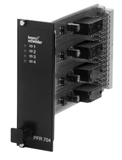
  • Plug-in function unit for mounting in 19" module subracks
  • Separate flame control for pilot burner and main burner by UV, ionisation or a further option of using the furnace chamber temperature
  • Programming and diagnostic software BCSoft simplifies logistics management
  • Display of the program status, unit parameters, and flame signal; manual mode for burner adjustment and for diagnostic purposes
  • Air valve control relieves the furnace control
  • FM approved
Documentation for PFU 780 Burner Control Unit

Documentation

Manufacturer's Product Brochure
Manufacturer's Operating Instructions
Manufacturer's Technical Sheet

 
Ordering information for PFU 780 Burner Control Unit

Ordering Information

Model Mains Voltage Trial for ignition period Air Valve Control Digital Input* Price
(US List)
Order Now
PFU 780LN 5/2 115 V AC 5 seconds Yes No $675 Buy the PFU 760 Burner Control Unit
PFU 780LN 10/2 115 V AC 10 seconds Yes No $675 Buy the PFU 760 Burner Control Unit
PFU 780LND 5/2 115 V AC 5 seconds Yes Yes $775 Buy the PFU 760 Burner Control Unit
PFU 780LND 10/2 115 V AC 10 seconds Yes Yes $775 Buy the PFU 760 Burner Control Unit
For all other configurations Contact Combustion 911

* Digital Input to interrupt flame monitoring.

Accessories

Model Description Price
(US List)
Order Now
BCU OPTO Opto-adapter (serial port connection) includes BCSoft CD-ROM $284 Buy the optical adapter
 
Applications for PFU 780 Burner Control Unit

Applications

Click on images for close-up view.

Application for PFU 780 Burner Control Unit Stage-controlled main burner with alternating pilot burner

Control: Main burner ON/OFF.

The main burner can be started with reduced capacity after the operating signal from the pilot burner has been detected. The pilot burner is switched off automatically after the main burner has started up. When the main burner is switched off, the pilot burner automatically switches on again.

A UV sensor monitors the flame signal from pilot and main burners. UV sensor UVD 1 is used for continuous operation, UV sensor UVS for intermittent operation.
Application for PFU 780 Burner Control Unit Stage-controlled main burner with permanent pilot burner

Control: Main burner ON/OFF.

The main burner can be started with reduced capacity after the operating signal from the pilot burner has been detected. Pilot and main burners can be operated simultaneously.
Application for PFU 780 Burner Control Unit Modulating-controlled burner

Control: Main burner continuous

The butterfly valve for air is moved to ignition position in order to start the main burner. The main burner can be started at low-fire rate after the operating signal from the pilot burner has been detected. The control system controls the burner capacity via the butterfly valve for air after the operating state has been signalled. Pilot and main burners can be operated simultaneously.
Application for PFU 780 Burner Control Unit PFU 780..D: High temperature equipment

The flame is controlled indirectly on the basis of the temperature. During the start-up process, as long as the wall temperature is below auto ignition temperature the flame must be controlled by conventional methods. When the working temperature has exceeded 750°C, the safety temperature monitor (STW) takes over the indirect flame control.
 
Specifications for PFU 780 Burner Control Unit

Specifications

Electrical Specifications
Mains voltage: 220/240 V AC, -15/+10%, 50/60 Hz,
110/120 V AC, -15/+10%, 50/60 Hz,
for grounded and ungrounded mains.
Power consumption: < 8 VA.
Control Inputs: Input voltage/current: Pilot burner, main burner, air valve, multi-flame control and remote reset: 24 V DC, ± 10%, < 7 mA per input.
Input voltage for safety interlocks, digital input DI and purge = mains voltage.
Input voltage of signal inputs: 110/120 V AC Signal "1": 80-132V (50/60Hz)
110/120 V AC Signal "0": 0-20V (50/60Hz)

220/240 V AC Signal "1": 160-264V (50/60Hz)
220/240 V AC Signal "0": 0-40V (50/60Hz)

24 V DC Signal "1": 24 V, ±10%
24 V DC Signal "0": < 1 V

Inherent current (Signal "1"): typ. 5 mA
Output voltage for voltage-related outputs: mains voltage
Contact rating: Gas valve V1, V2: Max. 1 A resistive; Max. 1 A cos ϕ 0.3

Air valve: Max. 1 A resistive; Max. 1 A cos ϕ 0.3

Ignition: Max. 1 A resistive; Max. 1 A cos ϕ 0.3

Number of operating cycles: Max. 1,000,000 typically 400,000; Max. 250,000, typically 100,000
Output current: max. 2 A per output, but total current for valves
and ignition transformer max. 2.5 A.
Number of operating cycles: Mains switch: 1000
Reset/Information button: 1000
Signalling contacts: max. 24 V, 1 A.
Flame control: Sensor voltage: approx. 230 V AC.
Sensor current: > 1 μA,
Length of sensor cable: max. 100 m.
Fuse in unit: F1: 3.15 A, slow-acting, H pursuant to IEC 127-2/5,
F2: 3.15 A, slow-acting, H pursuant to IEC 127-2/5.
   
General Specifications
Ambient temperature: -20 to +60°C (-4 to +140°F), no condensation
Enclosure: IP 20 pursuant to IEC 529.
Input/Output safety circuit: See connection diagrams in documentation
Weight: approx. 650 g (23 oz.)