Burner Control Unit BCU 480
The BCU (burner control unit) 480 controls, ignites, and monitors gas burners for intermittent or continuous operation. Its fully electronic design reacts quickly to various process requirements and is therefore suitable for frequent cycling operation.
It can be used for industrial burners of unlimited capacity that are ignited by pilot burners. Pilot and main burners can be modulating or stage-controlled. The BCU 480 monitors pilot and main burners independently. The pilot burner can burn continuously or it can be switched off. The BCU is installed close to the burner to be monitored.
On industrial furnaces, the BCU reduces the load on the central furnace control by taking over tasks that only relate to the burner, for example it ensures that the burner always ignites in a safe condition when it is restarted.
The air valve control assists the furnace control for cooling, purging, and capacity control tasks.
The program status, the unit parameters, and the level of the flame signal can be read directly from the unit. The burner can be controlled manually for commissioning and diagnostic purposes.
If the local requirements on the burner control unit change, the BCSoft software can be adjusted to the unit parameters of the application using the optical interface.
Users can see input and output signals and the error history.
Features
- For pilot and main burners of unlimited capacity in intermittent or continuous operation pursuant to EN 746-2
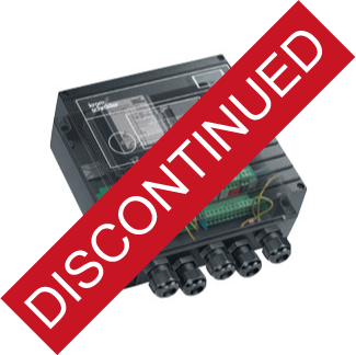
- Automatic burner control unit, ignition transformer, indicators, and operating controls are in a space-saving metal housing that replaces the local burner control cabinet
- Flame control is by UV, ionization or another option using the furnace chamber temperature
- Display of the program status, unit parameters, and flame signal
- Manual mode for burner adjustment and for diagnostic purposes
- Programming and diagnostic software BCSoft simplifies logistics management
- Spacious connection chamber with plug-in terminal blocks and plug-in cable sockets for quick installation and servicing
- Air valve control relieves the furnace control
- Optional PROFIBUS-DP interface
- EC type-tested and certified
- FM approved
 |
Documentation
Manufacturer's Product Brochure Manufacturer's Operating Instructions Manufacturer's Technical Sheet |
| |
 |
Ordering Information
| Model |
1st trial for Ignition Period |
Price (US List) |
Order Now |
| BCU 480T-5/5/2LR3 |
5 sec. |
$1260 |
 |
| BCU 480T-10/5/2LR3 |
10 sec. |
$1260 |
 |
| For all other configurations Contact Combustion 911 |
Accessories
| Model |
Description |
Price (US List) |
Order Now |
| BCU OPTO |
Opto-adapter (serial port connection) includes BCSoft CD-ROM |
$299 |
 |
| Ignition Cable |
Silicon Cable High Voltage 7mm (priced per foot) |
$3 |
 |
|
| |
 |
Applications
Click on images for close-up view.
 |
Stage-controlled main burner with alternating pilot burner
Control: Main burner ON/OFF
The main burner can be started with reduced capacity after the operating signal from the pilot burner has been detected. The pilot burner is switched off automatically after the main burner has started up. When the main burner is switched off, the pilot burner automatically switches on again. This reduces the main burner start-up time. A UV sensor monitors the flame signal from pilot and main burners. UV sensor UVD 1 is used for continuous operation, UV sensor UVS for intermittent operation. The BCU provides the cooling and purging processes. |
 |
Stage-controlled main burner with permanent pilot burner
Control: Main burner ON/OFF
The main burner can be started with reduced capacity after the operating signal from the pilot burner has been detected. Pilot and main burners can be operated simultaneously. This reduces the time required by the main burner for starting up. The BCU provides the cooling and purging processes. |
 |
Two-stage-controlled main burner with permanent pilot burner
Control: Main burner ON/OFF with ignition via bypass
The main burner can be started at low-fire rate after the operating signal from the pilot burner has been detected. When the operating state is reached, the BCU issues the Enable signal for the maximum burner capacity. Pilot and main burners can be operated simultaneously. This reduces the time required by the main burner for starting up. The BCU provides the cooling and purging processes. |
 |
Modulating-controlled burner
Control: Main burner continuous
The butterfly valve for air is moved to ignition position in order to start the main burner. The main burner can be started at low-fire rate after the operating signal from the pilot burner has been detected. The control system controls the burner capacity via the butterfly valve for air after the operating state has been signalled. Pilot and main burners can be operated simultaneously. This reduces the time required by the main burner for starting up. |
|
| |
 |
Specifications
| Electrical |
| Mains voltage: |
115 V AC, -15/+10 %, 50/60 Hz for grounded and ungrounded mains |
| Power consumption: |
approx. 9 VA plus inherent consumption of the ignition transformer (50/60 Hz). |
| Voltage to inputs and valves: |
mains voltage |
| Signal and control line: |
max. 2.5 mm2 (AWG 14) |
| Cable for burner earth/PE wire: |
4 mm2 (AWG 12) |
| Input voltage signal inputs: |
Signal "1": 80 - 126,5
Signal "2": 0 - 20
Frequency: 50/60 Hz |
| Inherent current: |
Signal "1" typ. 2 mA |
| Output current: |
Max. 2 A per output, but total current for valves and ignition transformer: max. 2.5 A. |
| Operation and fault signaling contacts: |
dry contact, max. 2 A, 264 V, not fused internally. |
| Flame control: |
Sensor voltage: approx. 230 VAC Sensor current: > 1 µA
Length of sensor cable: max. 50 m (164 ft.) |
| Fuse in unit: |
F1: 3.15 A, slow-acting, H pursuant to IEC 127-2/5 F3: 3.15 A, slow-acting, H pursuant to IEC 127-2/5 (on BCU..C). |
| |
|
| Ignition Transformer |
| Type: |
TZI 7-25/20 |
| Power consumption (115 V AC input): |
2.2 (1.6) A* |
| Power consumption (output): |
7 KV 25 (18)* mA |
| *values in parentheses apply to 60 Hz. |
| |
|
| Operation and fault signaling contacts |
| Signaling contact (not floating): |
max. 2 A, 264 V, not internally fused |
| Max. number of operating cycles: |
1,000,000 |
| Mains switch: |
1000 |
| Reset/Information button: |
1000 |
| |
|
| Operation and Environment |
| Length of Burner cables: |
max. 5 m. (16.4 ft.) |
| Ambient temperature: |
-20°C (-4°F) to +60°C (+140°F) (no condensation permitted) |
| |
|
| Construction Materials |
| Enclosure: |
IP 54 pursuant to IEC 529 |
| Housing: |
Die-cast aluminium with plug-in terminal blocks and plug-in M20 cable glands. |
| Weight: |
Approx. 5 kg (11 lbs.) depending on version. |
|