

An ignition transformer is a device used for direct spark ignition in combustion systems. Reliable, repeatable direct-spark ignition requires a high-energy spark — and the ignition transformer is what we use to generate the high voltage we need to create that spark.
A typical supply in the USA is 120 volts, but we need to send 6,000 – 20,000 volts to the ignition point of the burner, and the ignition transformer is what allows us to do that safely, and without taking up a ton of space. The utility of an ignition transformer is its ability to take a low-voltage electrical signal, provided by the burner control unit or flame safety device, and amplify it. The resulting high-voltage, low-current signal travels from the ignition transformer to the ignition electrode via special ignition cable, then down the length of the ignition electrode, terminating in a high-energy spark.
You may find an ignition transformer in a control cabinet, inside a flame safety or burner control unit, or in its own, dedicated enclosure near the burner.
You are likely to encounter both electronic and wire-wound ignition transformers on industrial combustion systems.
What is the difference between electronic and wire-wound ignition transformers?
Electronic ignition transformers use a circuit board to amplify the voltage, and can use a lower current to achieve high voltage.
Wire-wound ignition transformers use electromagnetic induction created by copper wires wound around two sides of a ring-shaped iron core to amplify the electrical signal.
How do wire-wound ignition transformers work?
The ring-shaped iron core has wire wraps on the primary power inlet and secondary power outlet sides. There are more wraps coiled around the outlet side of the core than the inlet side.
When it is time to light the burner, the flame safety unit sends power to the transformer. The electrical current travels through the copper wire on the primary side of the iron core creating a magnetic field. The electromagnetic force travels through the iron core to the secondary outlet side. The higher number of wraps on the outlet side compounds the magnetic field and causes the voltage to increase. The high-voltage signal travels through the ignition cable to the ignition electrode to light the burner.
What should my ignition transformer installation look like?
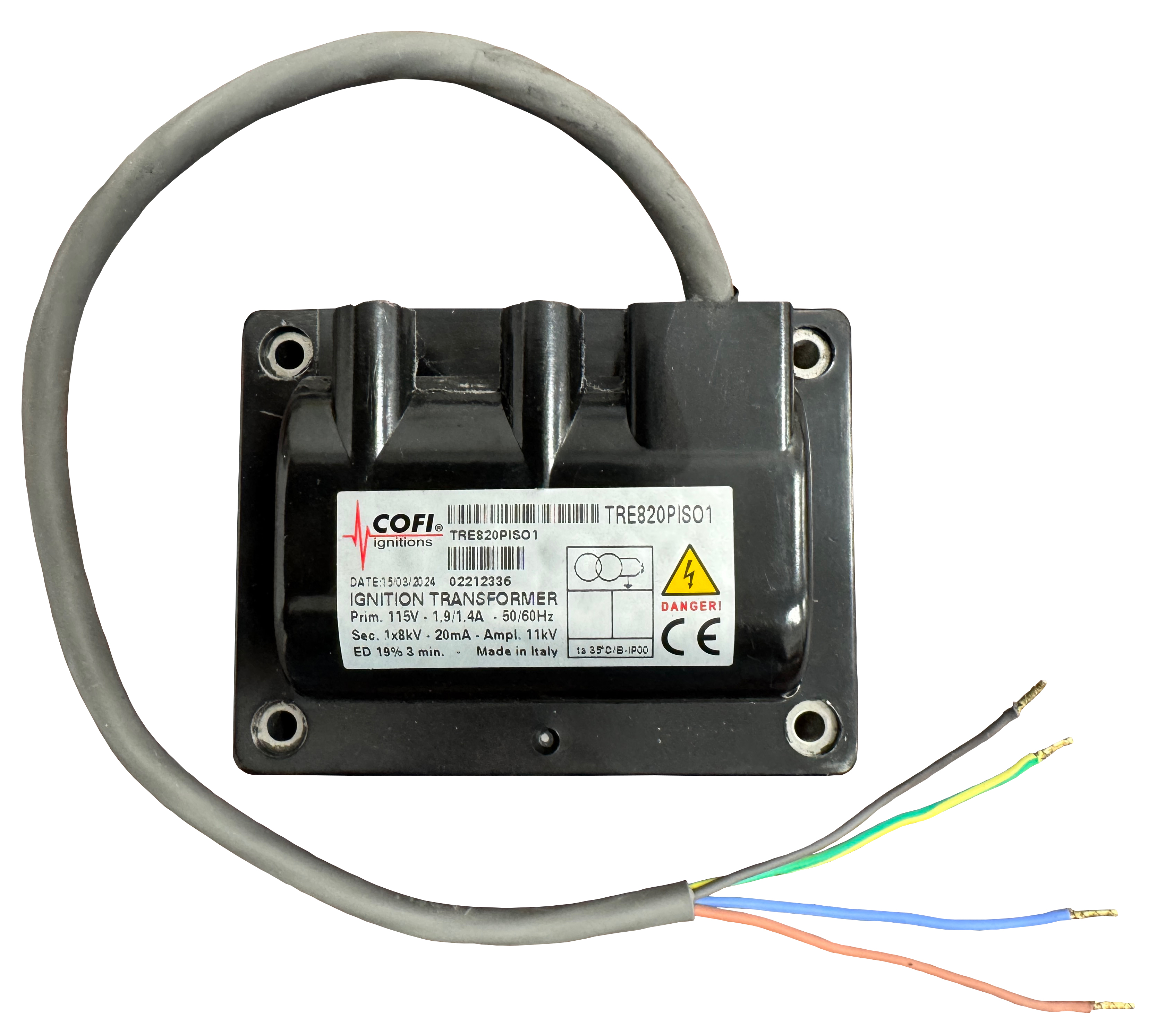
When installed, an ignition transformer should have two cables; ignition cable for delivering high-voltage to the burner, and the supply “pigtail” for termination at the flame safety device. This pigtail will include either (3) or (4) wires.
The ignition cable used for industrial burners must be rated for both high voltage and high temperature. Automotive ignition cable is not suitable for industrial combustion applications, as it generally contains a carbon core and is designed for a very brief spark. Ignition cable used on industrial combustion systems must be able to handle an ignition trial of up to 15 seconds.
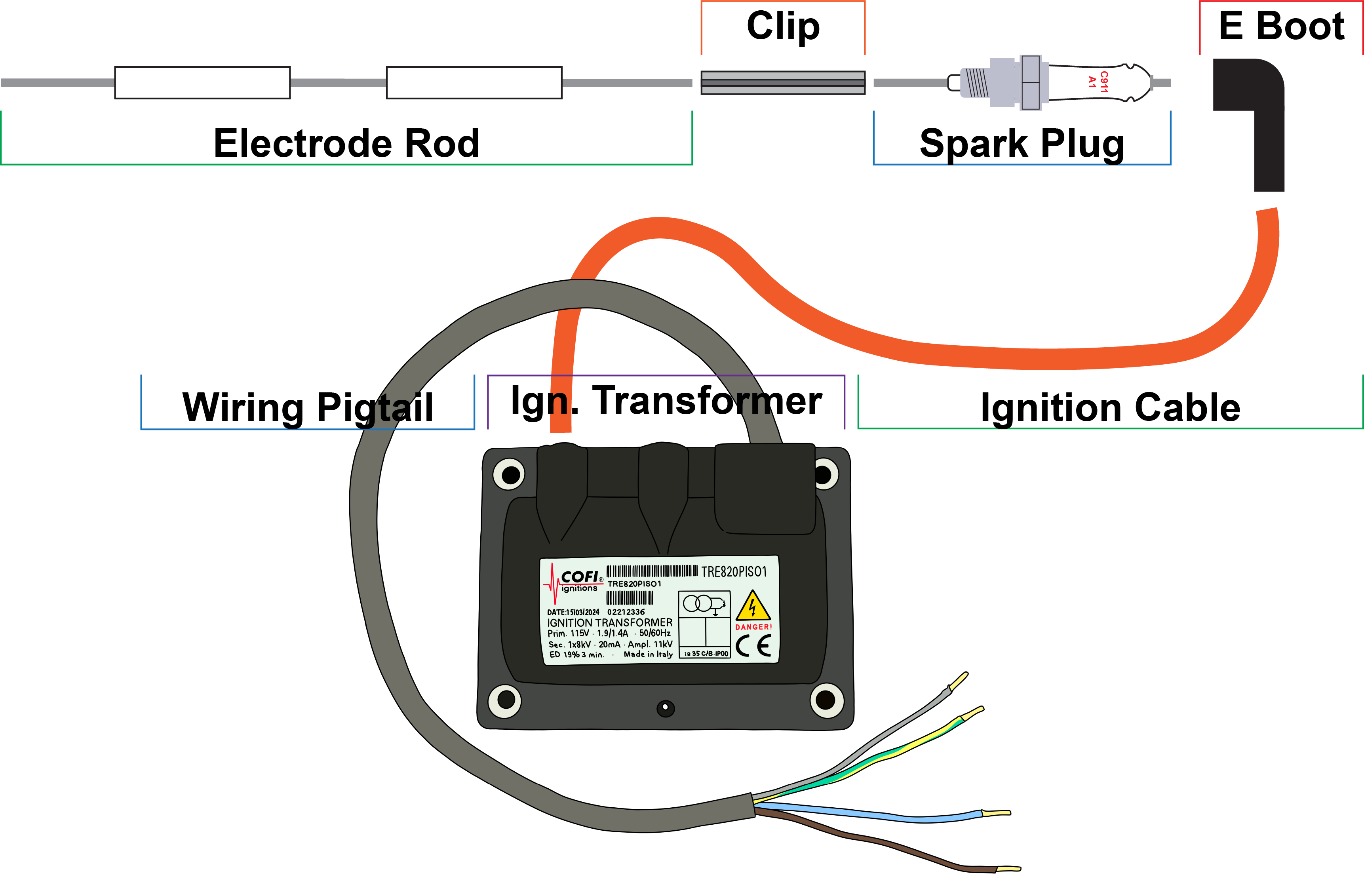
Transformer models with (3) wires serve a single function, providing high-voltage needed to light the burner. The (3) wires correspond to Line, Neutral, and Ground.
Transformer models with (4) wires serve two functions. Not only can they be used to provide the high-voltage needed for ignition, but they can also provide a flame detection signal back to the flame safety. In this design, the additional, 4th wire is insulated from the iron core and copper winding, allowing the low amperage signal to travel back through the transformer unimpeded.
Are 3-wire and 4-wire transformers interchangeable?
4-wire ignition transformers can be used in single-electrode systems, but they can also be used in dual-electrode systems, or systems where another method of flame detection is used, like UV. In these cases, the 4th wire is connected to either ground or neutral (normally ground).
3-wire transformers are not suitable for single-electrode (spark-and-sense) applications. A dedicated flame detection electrode, or some other means of detecting flame (like UV), is needed in this case.
What is a duty cycle and why is it important?
Duty cycle is the percentage of a defined time period during which a component (in this case, an ignition transformer) can operate (powered ON). Ignition transformers can operate, depending on the model, on continuous (100%) or intermittent (<100%) duty. Intermittent duty transformers are designed for specific ON and OFF times. Check the ignition transformer‘s label for specific data regarding duty cycle.
Examples of duty cycle notation, with explanatory notes:
ED=19% on 3 min. (180s)
The transformer can operate for 34 seconds and should be turned off for the remaining 146 seconds. Since the transformer is only active during burner ignition, and assuming a 5 second spark time, it appears the transformer can attempt six burner ignition trials in 180 seconds, or two per minute.
ED=25% on 4 min.
This notation means the transformer can be switched ON for one minute, and must then be OFF for at least three minutes. The total cycle time is four minutes, and the ON time is 25% of the total cycle time.
ED=33% on 3 min.
This notation means the transformer can be switched ON for one minute, and must then be OFF for at least two minutes.
ED=100%
These transformers can operate continuously.
Failure to adhere to the specified duty cycle can lead to overheating the ignition transformer, damage to internal parts, even catastrophic failure. Note, the duty cycle decreases proportionately if the transformer is subject to ambient temperatures in excess of the design specification.
In many combustion applications, 100% duty cycle isn’t required. However, a combustion system is custom-designed and therefore specification requirements vary. For example, some modulating systems run 24/7, for months on end, after ignition. Pulse-fire systems, on the other hand, may demand that burners light-off over and over again, during the heating process.
My ignition transformer stopped working, what can I do? Do I need to find the exact model to replace it?
Most ignition transformers do not have spare parts, and are considered “consumable.” That is to say, they are expected to fail at some point, due to deterioration from use. Therefore, you will have to replace them from time to time.
You do not need to replace the old transformer with the exact model. Get all the data you can from the failed transformer (a photo of the product label is the best way to start) and contact us.
What’s the right output voltage for my application?
Always check the burner’s recommended ignition voltage. You should find this data in the manufacturer’s technical literature. Some manufacturers may even note it on the burner nameplate.
High-voltage is needed to jump the gap between the electrode and the burner body, creating the spark that ignites the air/gas mixture, but there can be too much of a good thing. Excessive voltage can arc through insulating media, discharging prior to the ignition point.
It’s also worth noting that high-voltage is dangerous. The correct voltage can harm personnel if not shielded properly, and excessive voltage could cause even more harm to personnel and property. Using proper safety equipment, like electrode boots and high-temp ignition cable, in conjunction with the burner manufacturer’s guidelines, is crucial to a safe system.
How do I choose a replacement ignition transformer?
Here are the key factors to consider when selecting a new ignition transformer:
1. What is the input voltage?
2. How much output voltage is required?
3. What duty cycle is required?
4. Does your system use spark-and-sense (single electrode) for flame detection?
5. Where will the transformer be installed, does it need its own enclosure, or will it be inside the flame safety device or control cabinet?
6. Pay attention to the dimensions if you plan to replace an ignition transformer installed in an area with very little room around it. Can the new transformer be fastened to the base in the same way as the old? Most ignition transformer manufacturers provide dimensional data for this reason.

Interested to learn more about ignition?
FAQ: Ignition Electrodes for Pilot and Industrial Burners
FAQ: Electrode Adapters and Interference Suppression for Pilot and Industrial Burners
FAQ: Connecting Electrode Adapters to Ignition Cable


