

We’ve created a video demonstration to help users wire a DIN plug for an Elektrogas Proof of Closure device. The numbers in this blog correspond with the numbers in the video.
1. Once you’ve unscrewed the plug and removed it from the proof of closure device, step one is to remove the rubber gasket and set it aside.
2. Next, remove the screw. You will alternately push and pull the screw out of the plug. The inside of the plug isn’t threaded, so you don’t need to use a screwdriver in this step.
3. You will need a small, flat-bladed screwdriver to pop the connection block out of the plug housing.
4. The connection block is where you will install your wires. Push the wires through the plug housing before installing them to the connection block. Use your small screwdriver to loosen the screws you find on the connection block — all except the one marked with the Ground symbol.
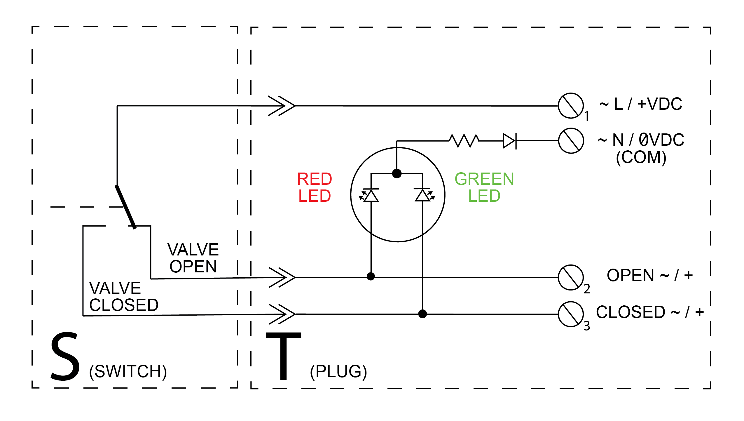
Schematic
5. This is the drawing found in the Elektrogas literature. The designations found on the right; 1, 2, 3, and COM, correspond to the markings on the connection block.
One is hot, Two is “valve open,” Three is “valve closed,” and the terminal marked “COM” is neutral in this case
The connection block contains a two-tone LED, to provide visual indication of the valve’s position. Once wired, powered, and connected to the proof of closure device, a red light means the valve is open; a green light means the valve is closed.
With the wiring complete, it’s time to reinstall the connection block in the plug housing. Feed the wires back through the plug housing until you can pop the connection block in place.
6. Proper installation of these three components keeps moisture from entering the plug housing. The rubber gasket must come first, followed by the metal washer, and finally the nylon nut. When using SO cord, keep openings in the insulated jacket on the terminal side of the rubber gasket. Any cuts in the insulated jacket which are on the other side of the gasket will allow moisture to enter the plug housing.
Replace the screw and gasket to complete your plug assembly.
For automation
Visit olstrad.com to learn more about our automation processes!


