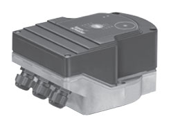
Combustion 911
Supplying and Serving the Combustion Industry
Phone: 330-678-8220
Email: support_ab

Actuator IC 40

Kromschroder Actuator IC 40The actuators IC 20 and IC 40 are for all applications that require precise, controlled rotary movement between 0° and 90°. They can be mounted directly onto the butterfly valve BVG or butterfly valve BVH to control gas and air flow rates on gas burners. They are designed for control ratios up to 1:10.

An optional integrated feedback potentiometer offers the option of monitoring the current position of the actuator. This scan function can be used in automation processes.

The IC 40 offers additional functions. It can be used in continuously controlled burners and in step-by-step-controlled burners.

Settings on the actuator IC 40 can be made using a PC with the software BCSoft. All the relevant settings for the process are made using the software via an optical interface. Various operating modes, which may be modified, are stored in the unit. In addition the control type (two-point signal, three-point step signal, or continuous control), running times, adjustment angles, and intermediate positions can be programmed.

The actuator can also be controlled manually using the software.

Once set, all the parameters can be saved on the PC and copied from there into other actuators, saving time during the commissioning process.

Service technicians can call up statistical data using BCSoft, such as hours of operation, actuating cycles, and an error history. Some values can also be set to zero, for example, to record data over a specific period of time.

Features

  • IC 40 for complex applications with programmable functions for flexible adjustment to the process, with statistics and error history to support service personnel
  • IC 20 for basic applications with continuous or three-point step control and automatic/manual mode changeover for easy commissioning
  • IC 20..E with electronic positioning function and adjustable behaviour in the event of cable break
  • A position indicator that can be read externally
  • Spacious connection chamber for ease of installation
  • Actuator can be mounted directly onto the butterfly valves BVG or BVH
  • UL listed
Documentation for Actuator IC 40

Documentation

Manufacturer's Product Brochure
Manufacturer's Operating Instructions
Manufacturer's Technical Sheet

 
Ordering information for for Actuator IC 40

Ordering Information

Model Safety Closing1 Torque Analogue input Feedback potentiometer Price
(US List)
Order Now
IC 40TA2 No 2.5 Nm No No $603 Buy the IC 40 Actuator
IC 40TA2A No 2.5 Nm 4 –20 mA No $644 Buy the IC 40 Actuator
IC 40TA2R10 No 2.5 Nm No 0 – 1000 Ω $691 Buy the IC 40 Actuator
IC 40TA2AR10 No 2.5 Nm 4 –20 mA 0 – 1000 Ω $746 Buy the IC 40 Actuator
IC 40TSA3 Yes 3.0 Nm No No $736 Buy the IC 40 Actuator
IC 40TSA3A Yes 3.0 Nm 4 –20 mA No $795 Buy the IC 40 Actuator
IC 40TSA3R10 Yes 3.0 Nm No 0 – 1000 Ω $820 Buy the IC 40 Actuator
IC 40TSA3AR10 Yes 3.0 Nm 4 –20 mA 0 – 1000 Ω $879 Buy the IC 40 Actuator
For all other configurations Contact Combustion 911

1With butterfly valve BVHS only

Accessories

Model Description Price
(US List)
Order Now
IC-20/40 ACC 01 Fastening set IC-BVG/BVA/BVH/LFC /B $8 Buy the IC 40 Actuator
IC-20/40 ACC 02 Attachment set IC 20/IC 40 single application /B $74 Buy the IC 40 Actuator
BCU OPTO Opto-adapter (serial port connection) includes BCSoft CD-ROM $284 Buy the optical adapter
For all other accessories Contact Combustion 911
 
Applications for Actuator IC 40

Applications

Click on images for close-up view.

Application for Actuator IC 40 IC 40, staged control

For processes that require a homogeneous temperature distribution in the furnace. The actuator IC 40 is controlled by a two-point controller and operates in On/Off or High/Low intermittent mode. The actuator closes when the voltage supply is interrupted. The running time can be adjusted between 5 and 25 seconds.
Application for Actuator IC 40 IC 40, staged control with three burner output levels

For processes that require a homogeneous temperature distribution in the furnace and three burner output levels. The actuator IC 40 is controlled by a programmable controller and works in High/Medium/Low or High/Medium/Low/Off intermittent operation. This allows the ignition stage to be started. The pressure switch provides failsafe monitoring of the maximum pilot air volume. The actuator running time can be adjusted between 5 and 50 (75) seconds.
Application for Actuator IC 40 IC 40, continuous control by three-point step signal.

The actuator IC 40 is controlled by the three-point step controller 3PS and moves the butterfly valve BVA to the ignition position. The burner starts.

Once the burner is operating, the operation signalling contact of the burner control unit BCU 460 closes. The BCU issues the Controller enable signal to the temperature controller. The butterfly valve opens or closes between the low-fire and high-fire rate positions depending on the capacity demand of the burner. When the three-point step signal is disconnected, the butterfly valve stops at its current position.

If both inputs on the IC 40 (DI 1 and DI 2) are actuated after the burner has been shut down, the butterfly valve closes further than the low-fire rate position.
Application for Actuator IC 40 IC 40, staged control with pre-purge

The central control system starts the pre-purge. Input DI 2 is actuated via the air valve output of the BCU and moves the butterfly valve BVA to the pre-purge position.

In the event of a temperature demand, the burner control unit BCU actuates input DI 1 via the valve output V1 and moves the butterfly valve to the ignition position. (Precondition: the IC 40 must have reached the ignition position on the instant of ignition.) The burner starts.

To activate the high-fire rate, DI 2 is actuated via the air valve output on terminal 26 of the BCU.

The butterfly valve moves cyclically between the high fire rate position and the low-fire rate position.
Application for Actuator IC 40 IC 40, continuous control with defined ignition position

The central control system starts the pre-purge. Input DI 2 is actuated via the air valve output of the BCU and moves the butterfly valve BVA to the pre-purge position.

In the event of a temperature demand, the burner control unit BCU actuates input DI 1 via the valve output V1 and moves the butterfly valve to the ignition position. (Precondition: the IC 40 must have reached the ignition position on the instant of ignition.) The burner starts.

The BCU actuates DI 2 via the air valve output. This enables the analogue input AI on the actuator IC 40. Depending on the capacity demand of the temperature controller, the butterfly valve BVA moves steplessly to the position between the low-fire rate and the high-fire rate as specified by the analogue input AI.
 
Specifications for Actuator IC 40

Specifications

Electrical
Mains voltage: IC 40: 100 – 230 V AC, ±10%, 50/60 Hz, the actuator automatically adjusts to the respective mains voltage;
IC 40T: 120 V AC, ±10%, 60 Hz.
Power consumption: 8.4 W
Switch-on peak current: max. 8 A for max. 10 ms.
Holding torque: Torque as long as permanent supply voltage is applied.
Angle of rotation: 0 – 90°, adjustable.
2 digital inputs: IC 40: 24 V DC or 100 – 230 V AC each,
IC 40T: 24 V DC or 120 V AC each.
Current requirement of digital inputs: 3 mA ± 1.5 mA.
1 analogue input (optional): 4 – 20 mA (IC 40T: Class 2) (internal load impedance max. 500 Ω at 20 mA).
Potentiometer (optional): 1000 Ohm +/- 20%, linearity tolerance +/- 2%, max. capacity 0.25 W (IC 40T: Class 2), conductive plastic element.
2 digital outputs: signalling contacts designed as relay change-over contacts.
Contact current of digital outputs: min. 5 mA (resistive) and max. 2 A.
Relay Contacts: The relay contacts can be connected to 100 – 230 V AC or 24 V DC (IC 40T: 120 V or 24 V). If the contacts have been connected with a voltage > 24 V and a current> 0.1 A once, the gold plating on the contacts will have been burnt through. This contact can then only be connected with this power rating or higher power rating.
2 LED status displays: Blue LED for operation “ON”, Drive in motion = Slow flashing light; Manual operation = Fast flashing light; Drive stopped = Permanent light.

Red LED for warnings and faults, Warning = Permanent light; Fault = Flashing light.

Red and blue LED simultaneously, Calibration in progress = Flashing light.
   
General
Enclosure: IP 65 pursuant to IEC 529
Protection class: impact-resistant and heat-resistant plastic
Electrical connection: Line entrance: 3 × M20 plastic screw connectors.
Ambient temperature: -20 to 60°C, no condensation permitted.